Business Trends | This is an installment of an ongoing, multi-part series. Be sure to watch for further installments in future issues! Click here to see multiple articles
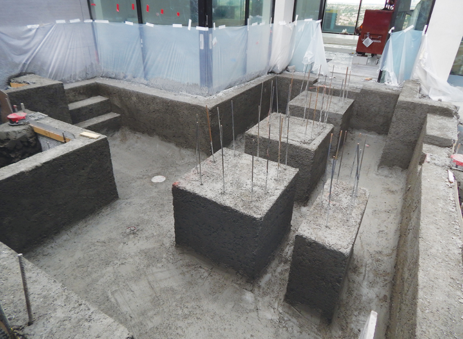
With the popularity of formal-entry and courtyard ponds increasing, the ability to incorporate proper system design is essential to long-term success. This project in particular was both a challenge and a joy to be involved with. The initial design showed it to be approximately 8,000 gallons with an L-shaped, floating stone walkway from the entry to the front door inside the courtyard. Planters were to be constructed on two sides of the pond, with the remaining sides serving as the foundation of the house. The owner-turned-contractor decided to install a shotcrete shell as one complete unit, eliminating cold joints and creating the planters at the same time.
Aeration Location
At 8,000 gallons, a turnover rate of 1-1/2 times per hour through filtration would be ideal. Space for equipment in the filter area was unavailable at the pond with no waterfall — just a small spill from a long trough constructed from an 8-foot H-beam. Placing equipment in the courtyard would have taken away from the formal, still-pond look. Fortunately, the filter room was located on the other side of the wall with plenty of space for filtration. The challenge was that the floor in the equipment room was 12 feet below water level. All the equipment needed to be pressurized, but at that depth, there was no way to aerate one of the filters for pond oxygenation. After much deliberation, a spot in the corner of the garage above the equipment room had space to place one biofilter at water level, allowing for it to be aerated.

Piping Predicaments
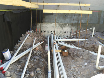
With all the equipment at or below water level, there was effectively no static head – only dynamic head. The number of pipes to and from the pond required 12 holes to be bored through the wall. The four bottom drains were each connected to individual 3-inch pipes to the filter room with no tees under the pond. These were tied together in pairs in the filter room to allow for individual cleaning as the pond matures. Each bottom drain had a 5-inch, fine bubble diffuser on its dome cover operated by an air pump on a timer. The return circuits were in sets of three 2-inch adjustable floor returns from 3-inch return piping. One skimmer received an electronic, automatic fill, and the other had a 1 ½-inch overflow plumbed to drainage outside the courtyard. The air discs on the drains each needed separate, ½-inch lines with air loops to prevent backflow, so the area of one raised planter just above the position where the holes were bored through the wall provided a good spot for this.
With all the major issues worked out, it was time to build. The contractors on-site and the superintendent were all amazing and worked quickly. One day later, I returned to find all 12 holes bored with nice rubber spacers placed in the holes ready for pipe. Four 3-inch drain lines, three 3-inch return lines, two 2-inch skimmer lines, one ¾-inch auto-fill line, one ¾-inch electrical sleeve, and one hole for all four ½-inch air lines were ready for pipe. A couple of days later, all the plumbing was laid out and stubbed into the filter room. I have to say that working with a plumbing crew that does houses instead of pools was a joy. These guys definitely knew the concepts of gravity flow and plumbing – like a toilet with no pressure compared to a toilet with pressurized plumbing.
Coping with Codes
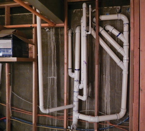
Because all the piping was consisted of individual runs, the inspector wouldn’t allow for each line to be pressurized separately. The plumbers had to create an elaborate manifold with all the pipes coming together into one gauge. The difficulty was that the piping needed to be behind the walls to hide it as much as possible in the equipment room, so they had to predetermine the initial direction of each pipe behind the wall and plumb accordingly.
Rebar went in and was inspected with only one issue. The bonding code had recently been changed. Instead of a No. 4 wire going from one spot on the rebar to the pumps directly, the new code required a complete loop around the perimeter of the structure. One short section should have been looped out into the surrounding landscape – approximately 24 inches – and back. The bonding wire assembly was connected to the pumps as before. Each stepping stone pillar required a No. 4 wire from the steps to the bonding loop. Pumps can generate a current that is transferred into the water column, so the new code ensures that there is no place on or in the pond where a current could flow from the water to someone’s foot. The code makes no allowance for polyuria, which completely insulates and seals the pond. I would consider this a good thing.
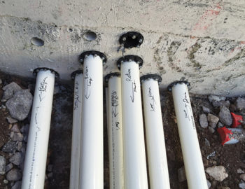
Drains and returns, left, were marked through the wall into the filter room. The photo on the right depicts a wider shot of the plumbing.
Once the pressure test was complete, the caps were cut, and the returns and drains were installed. This is one area that is different from pool construction. It is difficult to pressurize a pond drain line because of its design. In a plastered pool, the lines are cut after shotcrete, and the drains and returns are installed with the plaster coat. In a pond, the drains, returns and skimmers all need mechanical clamping faces for polyurea or other flexible coating. The floor returns have 2-inch threads and could have been installed and plugged earlier for the pressure test. Installing them after the rebar allows for them to be placed exactly at finished floor level.
Ready for shotcrete! In the next installment of this series, we will tackle the polyurea and the equipment room in detail.
Best Pond Practices | This is an installment of an ongoing, multi-part series. Be sure to watch for further installments in future issues! Click here to see multiple articles