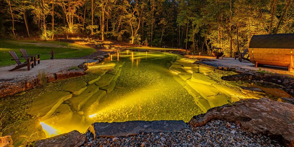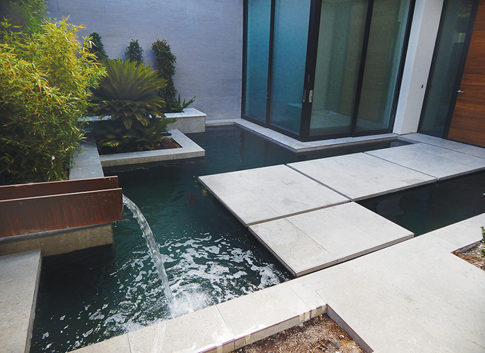
We’re back with the third installment of our series on the formal courtyard pond. This article is just one example of how to deal with this specific type of formal pond.
With the structure and basic plumbing in place, the polyurea liner can be installed. Polyurea is usually a two-coat operation, with the first application consisting of making sure any imperfections are taken care of. These are usually in the form of pin holes and small gaps around some of the penetrations. By coating the entire concrete surface with a cementitious product, such as Bond-Kote, the process is much easier. Shotcrete surfaces are usually very rough, and in standard pool construction, the plaster crew makes it all beautiful. But with any rubberized or plastic waterproofing, the surface must be smooth. The best way to describe the desired finish is a “sidewalk finish.”
Paul Parszik of Artisan Aquatics applied the polyurea. The isocyanate component has a reaction to chemical moisture in the concrete and to some additives in certain types of cementitious surfacing compounds. Normally a minimum cure time of 28 days is required, and depending on the environment and the type of concrete mix used, this still may not be enough time. We have experimented with many types of surfacing compounds over the years, and we have found Bond-Kote to be the best. Bond-Kote can be troweled very thin and hardens quickly, sealing the moisture in the concrete surface from the polyurea. Whatever Bond-Kote is made of, polyurea seems to like it.Once the polyurea is finished, all the penetrations get a mechanical clamping faceplate, just as rubber liner. Skimmers, bottom drains, returns and the auto-fill line all must be clamped. All nine returns are located in the floor and are adjustable, just like an in-floor pool return. In the past I have made these for polyurea by hand, which was very time consuming. I now have a molded unit that fits a 2-inch tapered return head. The polyurea is applied to the housing, and the clamp flange has a tapered top that fits the adjustable return insert. These nondirectional in-floor returns allow water to radius out in all directions from the return, evening out the flow around the floor. The auto-fill return is a ¾-inch fitting with a recessed flange specifically for polyurea, which can be used with rubber liner as well.
>> Related Content | Part 1, How to Rescue a Functionless Formal Pond
Filtration
Filtration for this project is divided into three separate circuits, each consisting of a pre-filter, pump and biofilter. The pre-filters are static suction pre-filters of my own design. These are sealed to be used above or below ground in a direct-suction configuration before the pump. The lower half of each pre-filter is a vortex settling chamber with Bacti-twist 300 in the upper chamber above a separation plate. The optimum flow rate is about 4,000 gph, with 6,000 gph as the upper end limit. The water enters through a 2 ½-inch side inlet and rotates in a vortex motion, allowing the heavier solids to fall to the bottom. The water, with the heavier solids removed, flows up through the separation plate and through the Bacti-twist, filtering out the finer particles before flowing to the pump. The bottom of the tank has a 2 ½-inch cleaning port and a water pressure inlet to blast the bottom of the tank. The separation plate has an air-blower cleaning manifold attached, and the top of the tank has three shower heads that blast downward during the backwash cycle.
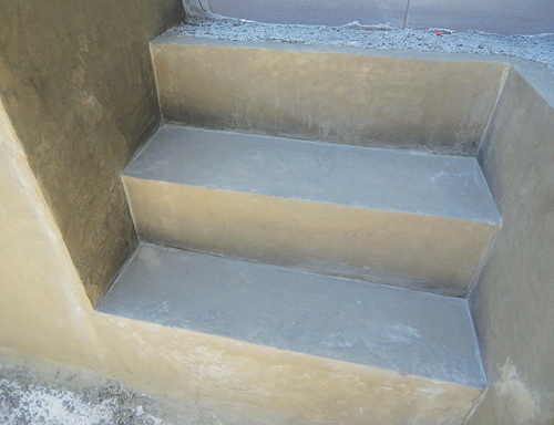
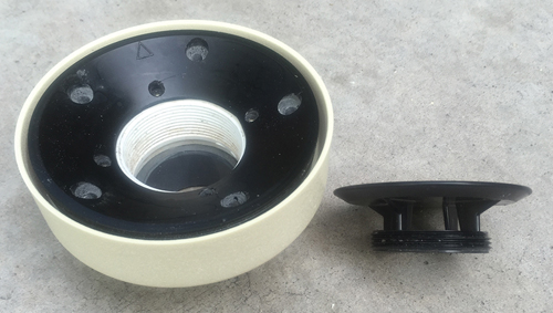
Bond-Kote is applied on the surface and 2-inch, adjustable floor returns.
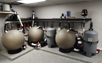
All three pumps are W. Lim Wave I 1/6-horsepower pumps at 4,000 gph each, for a total of 12,000 gph. Each pump uses only 2 amps, making for a very efficient and quiet system. The two biofilters located in the filter room are filled with both #100 and the finer-cut #50 Bacti-twist. Each contains a separate air cleaning manifold for blowing the debris off the media during the backflush and rinse cycles. Each filter is connected to the same main air distribution manifold the pre-filters are attached to. One 2-horsepower blower cleans all the filters. The circuit with the skimmers has a 58-watt Flo-Free UV light of my own design. Two of the four bottom drains flow through the second circuit in the filter room. The remaining two bottom drains flow through the third pre-filter and pump circuit up through the ceiling to the third biofilter at water level in the garage above.
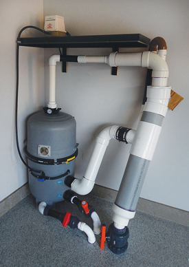
The third biofilter is the aerated system with a split internal design. The lower half is #100 Bacti-twist with the upper half consisting of 1 ½ cubic feet of Cermedia MP2c. The MP2c is aerated with a Medo air pump (45 liters per minute) with approximately 98,000 square feet of surface area for each cubic foot of media. Since most low-volume, low-pressure air pumps don’t operate efficiently over about 2 ½ pounds per square inch, it was important to place the internally aerated biofilter at water level to operate properly. It would not be possible for this filter to function 12 feet below water level. Once air is injected into the biofilter, it must be purged before returning to the pond to prevent air bubble restriction in the piping. Bubble restriction causes burping in the pipes and is visually disturbing. The air purge manifold is located just beside the filter and separates the bubbles out of the water column, venting them in the courtyard trough return. The water, purged of air, flows back down through the floor and returns to the pond through three of the in-floor returns. The aerated biofilter is cleaned by turning a three-way valve on the incoming air line, diverting air to the bottom for back flushing.
The only water feature in the pond design is a narrow-steel “H” beam trough paralleling the entry walkway that spills into the water as you enter the courtyard. The pump for this is a Wave I 1/15-horsepower unit that pulls water from the outlet side of the center pre-filter. A Medo air pump (80 liters per minute) on a timer sits on a shelf above the filters to supply the bottom drain air diffusers. The auto-fill is a Levelor electronic unit with the sensor inside the skimmer closest to the filter room.
A Quiet, Functional System
The filter room is used for other purposes and is adjacent to the downstairs recreation room. Creating a quiet system was important to the homeowner. The large piping with 2 ½-inch inlets and outlets on the filters keeps the dynamic head as low as possible, allowing for the use of the most efficient pumps available. The gauges on the tops of the filters don’t move and stay at a constant 2 ½ pounds per square inch, whether the pumps are on or off. My low-head pressurized biofilters help make this possible. The pressure reading on the gauge is the water pressure at the depth of water where the gauges are located.
Although this was a challenging system to create, it turned out well. As you enter the courtyard, the only sound you hear is the spill from the end of the trough return. Unexpectedly, the pattern of water flow can be seen easily around the in-floor returns as the biofilm and thin carpet algae began to grow on the floor. This visual pattern enabled me to easily adjust the returns as necessary to balance the flow.


