When I was asked to revisit the subject of pump hydraulics, I was honored — and a little intimidated. I immediately wondered how I could make this article in some way more interesting than the mathematics involved.

Let’s face it — as important as knowing what Total Dynamic Head (TDH) is, how to calculate it and how much money it will save you, I still may be the only person left who actually enjoys figuring it out. So, I wracked what brains yet remain after this challenging year to find a way to “Make Friction Fun Again.”
I decided to start with a discussion of the different types of pumps to explain why head calculations are needed in the first place. Then I’d try to make the steps — determination of flow, plumbing diameter, friction loss and Total Dynamic Head — as digestible as possible through simple visualizations.
Avoid Plumbing Pitfalls

The choice of pump and plumbing for any feature is often the most challenging decision a designer or contractor has to make. The wrong size or type of pump can turn a successful feature into a maintenance nightmare or an unaffordable money pit. The right plumbing is equally important. The wrong pipe diameter or poor fitting choices will destroy a powerful, well built, expensive pump in months, or even weeks. In order to determine the proper equipment, we first need to define the measure of the work to be done.
Pumps push water of varying volumes at varying rates upward against gravity and through pipe, battling friction every step of the way. We measure volume and rate in gallons per hour (gph). We equate the pressure a pump produces with the height it can push water upward in feet. One pound per square inch of pressure lifts water to 2.31 feet of “head” height. Using “feet of head” as the measure of pressure is convenient because we can add the height the pump raises water, or the Vertical Head, to the pressure required to force water through plumbing, or the Friction Head. The two combined, Vertical Head plus Friction Head, are the Total Dynamic Head (TDH), the total work any pump has to do in any given application. Once we know the TDH of any project, we can choose the right size and type of pump for the job.
>> Related Content | Tech Tip: How To Calculate Waterfall Flow
Direct-Drive Pumps
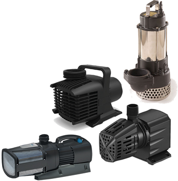
For every water feature, there is an optimal pump. Waterfalls that draw from the bottom of natural bodies of water or unscreened open reservoirs that aren’t maintained are best supplied by powerful direct-drive pumps with heavy impellers in oversized volutes, or so-called “trash pumps,” that can chop up debris and pass solids with ease. They have the power to drive water to great heights or distances, but they can be expensive to run. They have long been the go-to for many contractors who are predictably more concerned with trouble-free operation than operating costs, but they have to be carefully sized and plumbed. A high-volume, high-pressure pump that doesn’t have enough work to do will overspeed, cavitate and fail.
For high volume at low pressure, such as very wide water walls and waterfalls less than 10 feet high, axial flow pumps offer great efficiency. This type of direct-drive pump changes the design of the impeller and the direction of water flow inside the pump to offer great efficiencies at low head heights. In high-head direct-drive pumps, water entering at the front of the pump hits the face of a spinning impeller and gets slung out at 90 degrees at high pressure.
The axial-flow pump works differently. Envision a propeller in a tube. Water coming in the bottom of the pump gets accelerated out the top by a propeller-style impeller along the same axis without changing direction, hence the term “axial flow.”
The vertical style of both types can be a weakness. The top bearings, condensers and capacitors are located at the top of each pump and generate considerable heat. If the top of the pump isn’t completely submerged, the volute at the bottom will still draw and pump water, but the electronics will overheat and eventually fail.
Magnetic Induction
For water features that don’t have solids to chop up and have more modest volume or pressure requirements, like ponds with skimmers, magnetic induction pumps offer a number of advantages. By design, all mag drives eliminate the direct connection between the impeller and motor that gives “direct drive” its name. Direct-drive motors spin a shaft attached directly to a heavy impeller, necessitating bearings and shaft seals that cause power-robbing friction. Magnetic induction works on the principle that a magnet (or “rotor”) suspended inside a coil will spin when the coil is energized. Since there is no direct connection between rotor and coil, the coil that makes up the motor can be sealed in epoxy, with no power-robbing seals required. Lighter impellers mean less friction and less power required. Water circulating around the horizontal rotor keeps the motor cool. These pumps can be shorter and thus easier to keep submerged, so they are less prone to overheating in shallow water.
The cons? Magnetic induction pumps can’t handle large solids. They need relatively small intake screens or protection from a skimmer or pump vault to intercept debris (hence the nickname “clean-water pumps”). Also, the indirect connection between motor and rotor can’t provide the same level of pressure generated by a direct drive. These pumps are more efficient at providing high volumes, but at much lower head heights.
Magnetic induction pumps come in a variety of flavors according to rotor type and rotation. Simple magnetic rotors that spin in either direction are at the small end, producing low volume at low head. The larger stainless-steel-clad rotors of the asynchronous pumps drive very efficient impellers at a relatively low operating cost. With volumes of up to 10,000 gph at up to 10 feet of head and less than 1,000 watts, these have become the workhorses of the industry.
Recently, brushless DC pumps also have entered the field of water gardening. These pumps utilize the same type of powerful motor as those found in hard drives, cordless drills, Dyson vacuums and Tesla cars, using transistors instead of graphite brushes to increase efficiency and power. Electronic control of the rotating windings also means they can offer built-in variable speed control; some even feature pre-programmed patterns of higher and lower revolutions that cause the water flow to “dance.” (See Scene 1 above.)Their use is still reserved for larger pumps, as they are more expensive to produce, but the savings in operating costs often compensates for the higher initial price tags.
Calculating Flow

Regardless of pump type, which is determined by the requirements of the water feature’s design, the specifier needs to know what flow will be needed and the total work the pump will have to do. We usually use visual cues to determine flow requirements. The height or spread of the decorative spray of a fountain nozzle will vary with both volume and pressure, so charts specific to each nozzle are required. Open returns are easier to determine. Plug in the width of the flow and multiply by the required volume to produce the desired visual effect. Since the rate of flow (measured in gph per inch for water features) produces characteristic visual cues that we are all innately familiar with, a simple formula works for spillways and spouts, waterfalls and streams, bowls and boulders: width (inches) x gph/inch = Total Flow.
For a clinging flow where water adheres to a smooth vertical surface, you need around 50 gph/inch. An overflowing bowl with a rim 16 inches in diameter has a circumference of 16 x π (or 3.14) = 50 inches x 50 gph = 2,500 gph.
For a laminar flow, a smooth sheet of water falling off a smooth edge, you need at least 100 gph/inch. A 36-inch spillway needs 3,600 gph to produce a smooth curtain of water.
For turbulent flow, chaotic action and noise (usually characterized as whitewater), provide at least 200 gph/inch. A 30-inch-wide waterfall that needs to be seen and heard at a distance will need at least 6,000 gph.
Total Dynamic Head
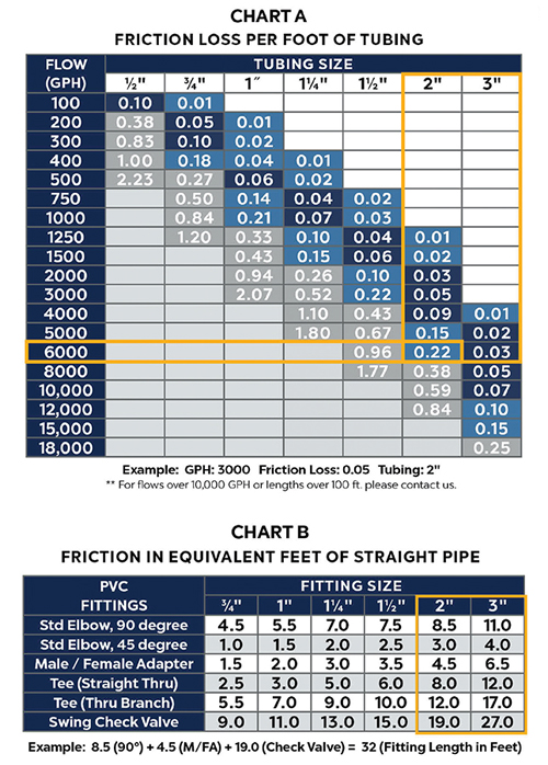 Once we select the flow required visually, we can figure out the TDH using the two tables shown on the following page. If you’d like to download a TDH worksheet, you can find one at www.atlanticwatergardens.com.
Let’s use, for example, a turbulent waterfall and stream 3 feet tall and an average of 30 inches wide, with a 50-foot run of pipe, a 90-degree elbow, male adapter and check valve. The flow required will be 30 inches x 200 gph/inch = 6,000 gph. We need only look at the larger table, which shows the friction of every foot of pipe for varying pipe diameters. With a straight run of 50 feet of pipe, 6,000 gph through 2-inch pipe will add 0.22 x 50 feet = 11 feet of friction head. By using 3-inch pipe, we drop the friction loss to 0.03 x 50 feet = only 1 ½ feet of additional head.
What about the fittings? Take a look at the smaller table on the next page, which converts the friction in fittings to an equivalent length of straight pipe. The 3-inch elbow, male adapter and check valve will add 11, 6 ½ and 27 feet of equivalent length to the 50-foot actual run respectively, so the corrected friction will actually add (44 ½ feet + 50 feet) x 0.03 = 2.8 feet of friction head to the given vertical head of 3 feet. Thus, the TDH is about 6 feet. Knowing the total work the pump has to do, we can look for a pump that will deliver 6,000 gph at 6 feet TDH, like the Atlantic TT7500 that draws 520 watts.
What would we be looking at if we went with the cheaper, easier-to-install 2-inch pipe? Well, the fittings would have added 8 ½, 4 ½ and 19 feet to the 50-foot run, creating an 82-foot equivalent length. The friction coefficient of a 2-inch pipe at 6,000 gph is 0.22, multiplied by the equivalent length makes 18 plus 3 feet of vertical head. Thus, we would have been looking for a pump that could provide 6,000 gph at a whopping 21 feet of head. This “more economical” 2-inch pipe would require the much larger and more expensive A-31 model, drawing 1160 watts — more than double the operating cost. The 3-inch pipe is the far wiser investment, and it will pay off handsomely.
Using the right size plumbing, you’ll select the right size pump for the job. It will cost less to buy and far less to run, perform better and last longer. If you or someone you know are still following the old rule of thumb of adding 1 foot of head for every 10 feet of pipe and 1 foot for every fitting, you would have come up with a guesstimate of 5 + 8 + 3 = 16 feet of vertical head. You would have had to choose the massive A-31 — and it would have cost you and your customer many hundreds of dollars unnecessarily.
Friends don’t let friends use rules of thumb. Calculate TDH. It’s money in the bank.