A few months ago, I was browsing a local pond and water garden site and answered a question asked by a woman named Sheila. She got back to me and asked if I could help with their new pond, which was part of a backyard makeover. Sheila and her husband Kelly wanted a formal raised pond that would be located at the east end of a new patio. A patio cover was to start halfway over the pond and extend west over the new patio. This was to be an outdoor entertainment area complete with a kitchen, television and seating area.
Coping with Challenges
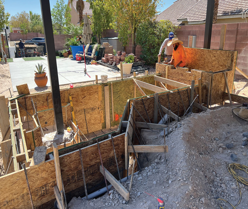
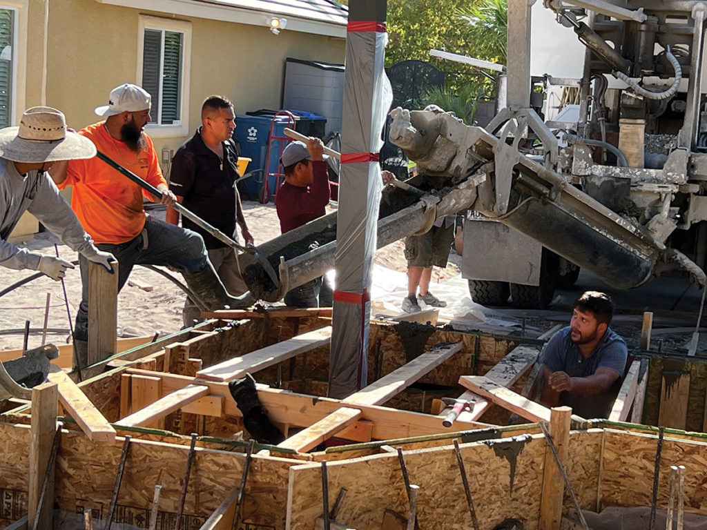
Before I became involved with this pond project, the company that was hired to build the outdoor kitchen suggested they build the same type of metal frame assembly for the koi pond. I was asked to help with the pond layout by creating a 3D SketchUp model they could work with. After several changes, it was determined by the project manager, Dave Case of American Precision Construction, that building the frame out of steel and covering it with cement board was just too complicated and expensive. The next option was to form and pour the walls out of concrete, which is the direction we went.
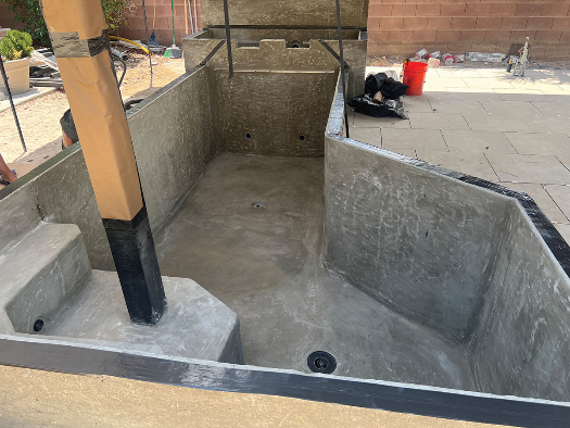
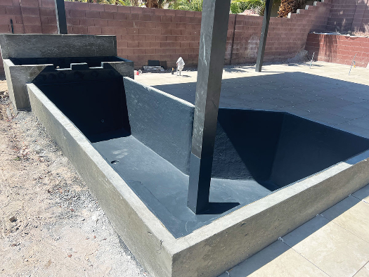
Another design issue we had to deal with was the two poles for the patio cover on the east end over the pond. One pole could be easily placed behind the upper bog and waterfall box, but the other pole was in the way due to the size and shape of the pond Sheila wanted. For no apparent reason, the patio cover contractor proved very difficult to work with when it came to placement and shape of the footing for that pole, so the decision was made to place the 6-inch square pole in the pond. It protrudes up through a plant shelf we designed into one corner of the pond’s end. The interior of the pond shell was to be coated with polyurea, making it easily doable.
The fish were temporarily placed in a small quarantine tank. A month after starting the design phase, it collapsed. I supplied them with another larger Polytank, and they were able to save their babies.
Design Specifics
The pond’s shape is a series of rectangles softened with a couple of 45-degree angles. One angle is the transition from the lower section to the middle section on the edge of the entertainment space. The other angle is in the corner where the pole comes up through the inside of the pond. With the pond at 4 feet of depth, this shelf was at ground level, so it clears the footing for the pole.
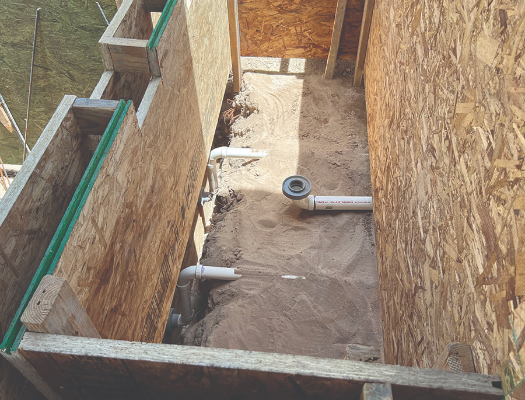
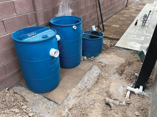
This corner is a two-tiered shelf that acts as the steps for egress. This end of the pond has a 3-inch LWS aerated bottom drain with a 5-inch diffuser and an Aqua-niche floating skimmer. Water travels from the 3-inch bottom drain to a 55-gallon drum radial separator behind the upper bog box with a Wlim Wave 1 1/6 Horsepower pump pulling from both the radial separator and the skimmer. Water will travel from the pump to two 55-gallon drum biofilters and back to the pond. The upflow sand and gravel filter will house a 3-inch down-flow UV light with a bleed port to prevent air buildup in the UV chamber. The other biofilter is an up-flow Air Driven Dilution Reactor with chunks of Matala as media and a 60-lpm Medo air pump to power it. Water from the ADDR will flow through a 3-inch line into the base of the upper plant bog with the sand and gravel filter feeding four 1 ½-inch returns. Two of the returns are near the pond floor at the base of the wall under the spills from the plant bog. The other two returns are at the far end, with one at the base of the plant shelf and the other on the shelf to promote good circulation through the plants.
In-pond aeration is from two 5-inch diffusers on a timer. One five-inch diffuser is on the bottom drain dome, and the other is a 5-inch diffuser cup in the center of the floor area. This second diffuser is in the middle section of the pond to help keep the floor circulated. A 40-lpm Medo air pump on a timer with a valved manifold supplies the air to these two diffusers.
Valving multiple air discs with a manifold is important because any fluid will follow the path of least resistance. A valved manifold gives you the ability to restrict the air supply to the discs or stones with the most flow, which balances the flow equally between the two air discs. You will always have one valve wide open, because that will be the air line with the most restriction. The key to making an effective air manifold is finding small enough valves. Finding standard valves smaller than ½ inch is easy, but they are usually much more expensive. I’ve had the best success using CPVC valves, because these ½-inch valves have a slightly smaller inside diameter, making the air adjustment easier. Using standard ½ or ¾-inch valves makes the manifold hard to adjust, because the hole size is so large that you must close them way down to effect any change.
The upper bog box has a support plate about 4 inches off the floor, just the same as an up-flow sand and gravel filter. This allows for a more even distribution of water throughout the bog and makes draining and cleaning easier through the 2-inch bottom drain, leaving it unrestricted. The support plate assembly is made of heavy-duty plastic shelving cut to fit. Just above the plate and under the first layer of large rock is an air-cleaning manifold to blow the rock and gravel clean, allowing the bog to be drained from an upper rinse drain.
Finishing Touches
Once the forms for the shell were removed, the interior surfaces were cleaned and parged with BondKote to prepare the surface for the polyurea. Paul Parszik of Artisan Aquatics was hired to apply the polyurea coating. The raised outside surface of the pond is covered with black tile, while the bog box is covered in a lighter-colored ledge stone. A 1-inch angle aluminum step was sealed in the polyurea to allow a starting point to set the stone on the inside of the front face of the bog and on the face under the spills leading from the bog to the pond. The top cap sections are custom-poured concrete according to Sheila’s dimensions.
It was nice to work with a client who knows what they want and has a specific vision. It’s also great when that client can see a construction issue and deal with it accordingly. There were other issues not related to the pond that came up, and watching Sheila and Kelly deal with those in a constructive and cooperative manner makes me wish all my clients had that ability!