Creating an airlift system to both circulate water and oxygenate a system at the same time is one of my favorite pond construction techniques. Almost any pond can be built using an airlift system in some fashion, but formal designs lend themselves to airlifts more often than garden designs. Formal ponds are generally located in courtyards or implanted in hardscape with a small spill or no water feature at all. Using airlift circulation can be an important asset, allowing full oxygenation without the use of a waterfall or the constant visual appearance of a column of bubbles in the water.
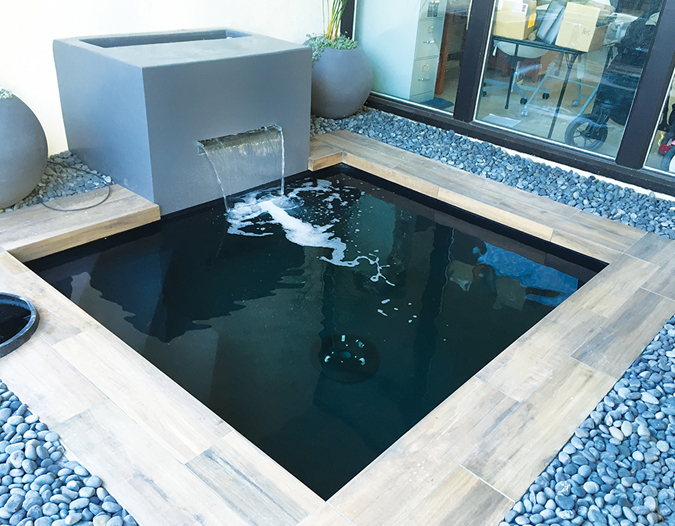
Recently, I received a call from a new client who wanted a small koi pond at the entrance of her home. She was remodeling her home in a very contemporary style and wanted to manage and construct as much of the pond as they could themselves, just as she had done with the rest of the remodel. The only water feature was a small spill against the wall. I supplied a basic plumbing layout along with the parts, equipment and installation instructions, and she ended up doing an excellent job. Even though she didn’t completely understand how the airlift system could work without a mechanical pump, she went along with it. I promised her that if she were to construct it just as I had proposed, all she needed to do was to plug it in, and it would work.
A Game of Twos
There were two issues to deal with: first, the lack of any space out of plain view to place equipment, and second, the above-water spill feature. The spill was to be approximately 24 inches wide and about 18 inches above water level. A living water feature with the still-pond, formal look needs both oxygenated filtration and fine particle removal, so I proposed a split system.


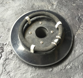
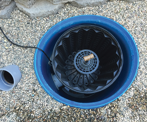
Far left: Prefilter and aerated biofilter with airlift. Middle: Vertical pond return drain with air ring.
The bottom drain would connect via a 3-inch, gravity flow pipe to a 55-gallon drum prefilter. From the prefilter, the water would flow into an airlift-operated, downflow biofilter and back to the pond. The media in the downflow biofilter was to be oxygenated, which makes it difficult to trap fine particles, so I proposed an upflow-sand and gravel filter system for the spill operated from a submersible pump in the skimmer. With only 18 inches of room between the wall and pond shell, there wasn’t much space for the filtration against the wall and nowhere else to hide an above-ground filter. A skimmer needs a minimum of approximately 1,500 to 2,000 gph to operate well, which is fine for a 55-gallon drum-sized filter, but one 30-gallon drum wouldn’t flow enough to work. Thus, I went with a pair of 30-gallon drums at 18 inches in diameter.
>> See more Pond Best Practices on motors, filtration and design challenges
I provided the upflow-sand and gravel filters built using a pair of 30-gallon drums and connected the spill to the fronts of both. Finding a stainless spill that would work proved difficult, because most stainless spills come with a 1-inch inlet that is too restrictive for a gravity-flow system. The client ended up ordering a spill that I modified by blocking the 1-inch inlet and adding two 1.5-inch bulkheads that barely fit.
I have cut up my share of spills over the years to adapt them to gravity flow. It would be helpful if one of the manufacturers would make a stainless spill series with inlets large enough for gravity flow. A pair of 1.5- or 2-inch, threaded bungs would be perfect, as they easily can be bushed down or blocked, if necessary.
Operation DIY

The customer used her landscape crew to dig and trench for the pond, filtration and plumbing. They hired a concrete company to do the rebar and shell and managed the inspections without a hitch. I gave them a list of things the inspectors would be looking for. The pond was to be fairly square, so steps for egress were formed in one corner, and the existing courtyard lighting proved enough to pass the lighting requirement. They coated the surface with Herco rubberized pond coating, because they could do that themselves. The drain, skimmer face and returns were all mechanically clamped, as you would do for liner or polyurea.
Water from the airlift biofilter returned to the pond in two ways: one 3-inch line that returned through a vertical pond return through the center of the drain, and a 2-inch line split into two 1.5-inch returns in opposite corners. This allows most of the water to return up through the center of the pond with just enough coming in through the corner returns to create a slow rotation.
The upflow sand and gravel filters and spill assembly were encased in a cube of concrete with just enough of an opening in the top to access the filters. A 40-watt ultraviolet light assembly of my own design was installed in a downflow configuration in one of the sand and gravel filters to keep it out of view. I like hiding UV lights inside biofilters because it makes mounting and hiding them much easier. When installing a UV light in a downflow configuration, it is important to drill a small vent hole at the top to allow air along with a small amount of water to escape back into the system. The small vent hole prevents the entrapment of air, which can gradually form an air space that displaces water in the housing.
Air Traffic Control

The prefilter is one of my 55-gallon drum, static prefilter kits modified slightly for an airlift. While the inlet line from the bottom drain is 3 inches, the outflow from the prefilter basket and the connecting pipe between the prefilter and biofilter are 4 inches to promote better flow and lower pipe friction between the prefilter and airlift. The upflow airlift pipe is also 4 inches, so it makes sense to keep them all 4 inches. The basket screen outlet in the center of the prefilter has a valve made into it to isolate the tank when cleaning. This eliminates the burying of a 4-inch knife valve between the filters along with the expense of the valve. Water travels from the prefilter through the side of the biofilter tank at its base directly into the airlift. At the top of the 4-inch airlift upflow pipe sits a horizontal diffuser, which pushes the water out in all directions over the media in the filter.
The air coming from the air pump is split into two lines, one for the airlift and one for an air ring around the outside of the airlift upflow pipe. This air ring oxygenates the media and creates an upward and downward flowing motion in the tank, acting much like a moving bed with no floating media. I’ve called this system an Air-Driven Dilution Reactor, or ADDR. My media of choice for these is Bacti-twist because of its free-flowing nature and ease of maintenance, but many different media types can be used. I’ve built several of these filters with moving bed media, and moving beds are much more manageable in a downflow configuration.
No matter what the media choice is, water travels up through the filter media, around the center and down through the media along the outside in a continuous cycle. The water exiting from the top of the airlift diffuser mixes with the water coming up the center of the filter and flows across to the outside, where it flows to the bottom. The cycle continues with the volume of water generated by the airlift exiting through the lower support plate and back to the pond. The air bubbles in the airlift and the ADDR are purged in the biofilter, with the water returning to the pond stripped of bubbles.
The only other accessory for the pond is an aeration ring on top of the bottom drain cover. This diffuser ring is operated by a small air pump on a timer to come on occasionally, or to be used as a backup in case of emergency.

Placid Perfection
This may sound complicated, but the end result is a small, formal pond in a courtyard with no visible equipment except for two small air pumps and the power supply for the UV light against a separate wall. At 9 by 8 feet and just under 4 feet deep, this pond is approximately 2,100 gallons, with the only motion a small spill at one end. It’s very much a still-pond experience, and my do-it-yourself clients did an excellent job.


